I’ve been tinkering with tDCS for several months now – including doing lots of reading and building of prototype devices. I also have a number of friends who are giving it a try. Along the way I’ve learned a number of things that could be useful to others:
1. Read, read, read. Lots of tDCS articles and dialog are on the web and more every day.
2. Seek professional help with tDCS if at all possible. For example www. transcranialbrainstimulation.com
3. Safety first! Read mine and other articles about tDCS safety. http://www.speakwisdom.com/tdcs
4. The popular ActivaDose II seems to be a good device for tDCS – a bit “edgy” in its current regulation – which may be irritating to some
5. tDCS devices built around the LM334 seem to work very well and provide very smooth adjustments to current level
6. Information on treatment montages is a bit scattered, but getting better (see my doc below for a start)
In conjunction with the above, here is the schematic I use to build devices to tinker with. There are many other designs on the web.
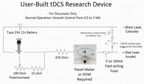
(This is my favorite design. Simple, smooth, works.)

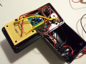
(Almost done. A bit more soldering…)

(Completed except for labeling. Simple, solid, reliable!)
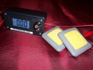
(Digital meter in place of analog.)
(Same basic design, just digital mA meter.)
And finally, here is a link to a bit of doc I’ve written for use with the home-built tDCS research device and ActivaDose II.
Comments and suggestions are welcome.

Excellent! Thank You!
Did you see a difference in the waveform for the ActivaDose II device compared to the DIY LM334 circuit?
Did you notice a difference in the sensation (burning, flashing) for the ActivaDose II device and compared to the DIY LM334 circuit?
Very nice entry, thanks for the information.
My observation is that the LM334 produces a much cleaner output than does the ActivaDose II. Again – my observation: The ActivaDose II produces more flashes and irritation than does an LM334 based device.
See http://www.speakwisdom.com/tdcs for an article I did on tDCS and ripple.
Brent
How would you compare the Activa Dose II output to the Brain Stimulator? The price of the latter is quite compelling. Though I did receive good effect with the former.
They both do basically the same thing, but the Activa Dose II has many more features including a timer, current monitor, a boost circuit to help it overcome skin/hair resistance, etc. I do find the current regulation of the Activa Dose II to be “edgy” and a bit uncomfortable for some.
Brent
The output from the Activa Dose II is in my experience “harsher” than that of simple tDCS devices not employing a voltage boost circuit (like the Brain Stimulator.) The Activa Dose II is more sophisticated and offers nice features like session timing.
Brent
While surfing the Inteernet about TDCS and CES, I found a site called TransHumani.com that linked to a forum portal, where a member discussed unit he had built (and sold). Seemed to be quite knowlegeble ob the build process and implementation. Unfortunately I wasn’t able to register on the wiki sitein order to contact him. The post is “CES/TDCS Devices For Sale” at http://transhumani.com/topic78.html .
you didnt answer my question but it was a stupid question, anyways where did you buy the digi meter, I’ve built the exact device base on your schematic and per your documentation have begun to to do savant stimulation.
My real question would be, where do i stimulate to improve my math and problem solving skill, since i’m a mech engineer student and we solved a lot of math and Force equation…if you know what I mean?
Sorry – I missed the questions. You can buy the digital meters on EBay and Amazon. I get the 0-20 mA meter.
I’ll have future posts regarding electrode placement based on studies published on the web.
Brent
I wonder what happens if you go beyond the 25 min recommendation time, and go for like a full 8 hour like sleep and leave it on all night?
I have no idea, but would not recommend it.
Brent
Well in my experience:
Firstly, your sponge electrodes- you should be using sponge electrodes- will dry out long before the 8hr mark. Unless you’re in a rainforest or something.
Secondly, the longer you continue a run the greater the chance one of your electrodes will come part-way off and possibly give a significant burn before you awake. This is very unlikely with sponge electrodes at least.
Finally, after a run of 1, 2 or 3+ hrs you’ll feel a bit like a hangover is passing. There are almost certainly chemicals like neurotransmitters and nutrients being exhausted in the effected cells which will need to be replenished.
It’s far from clear how long an “ideal” run should be or the rest required thereafter. 20-20mins is entirely reasonable yet it’s status as the Norm is more to do with the nerve of the earliest experimenters than anything else; that’s what they did and so the literature consists of the replications.
At some point there will be good information on effects and consequences of various durations and current densities, montages, even wave-forms and frequencies- but not yet.
PS, ’20-20mins’ should’ve been 20-30mins.
While I’m at it I should stress that I saw no particular benefit to runs of ten times longer than standard practice. It’s difficult to say without large scale replication of blinded trials but the only obvious difference is that sense of a fading hangover, which feels less like one fading the longer you go.
There are studies already completed that show diminishing returns after 20-30 minutes of treatment. I haven’t seen anything that indicates longer treatment time adds value.
Brent
Good to know, thanks. BTW, does that apply to both anodal and cathodal stimulation?
Please excuse my ignorance on some of this. I understand the basic principle of TDCS, the current flow and most of the parts, but am a little confused on the electrodes. Many articles talk about Anode and Cathode electrodes. Is it the type of material inside the electrode that determines if it’s one or the other? Or, is there some other factors? When I looked up sponge electrodes on the Internet, the descriptions do not appear to have any reference to the electrode being Anode or Cathode. Do electrodes come individually or as a set and when looking at the electrodes, how do you tell the difference? Thank you!
Hi Dave,
The anode is the positive electrode, the cathode is the negative electrode. Electrodes seem to be mostly sold individually – so two must be ordered.
Brent
But is each electrode somehow identified as Anode or Cathode. Maybe I’m missing something, but the online sales sites don’t seem to identify the electrodes as being Anode or Cathode. As Iunderstand it, the current flow process is determined by wether the ANode or Cathode electrode is connected to the positve side (hopefully I said that right).
The anode is the electrode connected to the positive lead of the tDCS device. The cathode is the electrode connected to the negative lead of the tDCS device.
Brent
The electrodes are interchangeable. It doesn’t matter. You attach the electrodes to the cathode and anode. Therefore they become either the cathode electrode and the anode electrode. The charge going through the electrodes is what makes it negative or positive.
I would like to see a source list made of the components and a reliable supplier. Construction techniques would be very useful too. Your hard work is appreciated.
You should find my latest post helpful.
Brent
Which post is that? I am looking for a BOM for this, as most of it seems to be Radioshack parts (though I don’t see a 100-Ohm pot at Radoshack)
100 ohm potentiometers are available from several vendors. Google search to find the best deal.
Brent
Which post? I took a look at your blog post directly after this one (https://speakwisdom.wordpress.com/2013/02/26/introduction-to-tdcs-devices-treatment-and-more-part-1-of-many/) and didn’t see anything on parts. Where did you purchase the case for your analog model? Do you have a part number for the case? Your hard work is much appreciated.
There are many parts sources on the internet (including ebay and Amazon.) The case I used came from Radio Shack.
Brent
Hi Brent, forgive my ignorance of electrical engineering, but is your current control knob attached to the potentiometer? I’m assuming that the pot is what you’re using to control the current with the LM334. Or am I sorely mistaken?
Yes – to a potentiometer.
Brent
Ace!
I need a back up machine. I do tdcs everyday at least 2x a day 8 hours apart different montages. Depression, motor cortex and language area (behind my left ear).It has changed me. I feel as if my brain is doing better than before i did tdcs. A bit faster, i am not depressed, I am afflicted with bipolar 2 depression. when you suffer from an illness that results in 20% of those afflicted trying to kill themselves and 11% doing so something that works is so great. It REALLY helps with pain. Not to make this available to people suffering is a shame. Of course I am very lucky. extrapolating from various studies is at best hit or miss as to what will really happen to you. I have also made mistakes. Fortunately I make an effort not to do anything that i find uncomfortable twice. So I must say please try to do this right. Consistency seems to reinforce neuroplasticity. I know that this empirical approach probably rubs the theorists wrong but I am your lab rat. Thanks for your excellent work.
Oh yeah my verbal memory seems increased and oddly enough my handiness that is I have been very left handed but now not as much. supposedly this is due to tdcs’s influence on the motor cortex.
I have procured a tdcs device. My doctor gave me tdcs for depressio for 8 days, helped me alot. I am gonna do it on my own now. Do u recommened tdcs everyday for a couple of hourss?? is it safe if done more than an hour??
Hi Shan,
I don’t prescribe tDCS treatment scenarious. You need to do some serious reading on tDCS and current practices. Most users stay with the research norm of 20 to 30 minutes up to several days per week.
Best of luck.
Brent
Bob Beck said when using CES stimulation more than 40 minutes per session will negate the positive effects. As John A stated above long sessions will deplete your neuro chemicals…Dr. Bob Beck recommended 20 minutes 1 or 2 times daily.
Alex – Exactly which device were you using? I want to be sure the one I buy (for me, my first device) gives me results as least as good as yours, as I suffer from similar issues to yours. Thanks!
I use a Chattanooga Ionto and have a Dupel which is the same thing, as a backup. Any iontophoresis machine with similar specs would be fine too. You have to get Arex sponge electrodes separatly and attach bannana plugs instead of the clips that it comes with. Easy to do.
could we get a higher resolution view of the schematic? I cannot read the text around the switch or LED.
I’ll try to make a more permanent link on my blog. But for now, here is a link to the schematic in my Dropbox.
Brent
Thanks! I built it, but I have not tested it yet, as my electrodes have not arrived yet.
I have built this device. When I test it with a 5k resistor or larger as a test load, it operates as expected, turning the pot changes the amperage between .5 mA and 2 mA. If I use a resistance much lower the max current will be higher. Is this the correct operation for this circuit?
That is when I use a resistance lower than 5k turning the pot all the way to the right creates a current higher than 2mA.
where did you find a digital meter that could monitor a 1mA current? all the affordable ones i ve seen wouldn t go under a 200mA sensitivity
Check EBay. They have analog and digital meters that will read very low current levels. I’ve seen some on Amazon, too.
Brent
Huh? Excuse me but even the $5 throw-aways sold at Harbor Freight read my 2mA output with several of them all agreeing to within 10% or so of the same value.
I believe this is one.
http://www.aliexpress.com/store/product/0-36-Digital-Ammeter-Red-LED-Display-DC-0-20-00mA-Current-Measurement-Amperemeter-Ampere-Meter/402798_676925798.html
That looks like it will work.
Brent
SpeakWisdom, can you please post pictures of your device interior?
All of my constructed devices are in use. Interior photos will have to wait till I build another.
Brent
This is great.
2 things:
1. what does it say above the red lead, anode on your circuit blueprint?
2. why does the Reddit Tdcs unit have the meter before the LM334 and the potentiometer?
Wouldn’t that mean you schematic is the only correct one because it is able to varying the current prior to a readout from the meter?
Hi Ron,
Sorry it does not show up better. It says “LED & Resistor pair. Suggest RS 276-0209”.
Brent
SpeakWisdom, can you have a look at this design, it is basic but I need something like this to start with.
I made it just like this guy and it works, question is is it done the right way?
This is the right link
it keeps posting the wrong video, the title is “My tDCS device” and if you type it on you tube it is the first one from the top
Hi, need help with electrodes. How large? Can you/should you use larger electrodes to effect greater area. I’m particularly interested in cath for reducing cortical hyper excitability. How do you maximize electrode contact thru thick hair? For cath where should one place anode? Again reducing excitability is key.
Any thoughts would be appreciated.
Most that I am aware of are using Amrex 2×2 or 3×3 electrodes available from Amazon and many others. They are sponge electrodes that you wet with saline. Seem to work well through hair.
Brent
Hello Dr. Williams. I’m a novice with electronics. Can you recommend a source for learning circuit building? I have a few questions about how/why the circuit is built the way it is. Like, why is there a 15 Ohm resistor after the pot?
Thanks!
Hi Neil,
That resistor is present to make sure the resistance between the two leads can not go to zero, thus limiting the current range of the regulator.
I don’t know of a specific electronics tutorial site, but I’m pretty sure you could find a few via a Google search.
Brent
hi how do i make this, could you upload a video or step by step guide on how to build this? thanks tom
Hi Tom,
I have no plans to make available more detailed construction guidance at this time. You might want to take a look at the commercial products now coming into the market, some very inexpensive.
Brent
Hi Brent,
Do you know of any devices coming out that we don’t know of?
keith
Hi Keith,
No – I’m not aware of anything that is not already “out there”. Hopefully some new tDCS devices are on the way though.
Brent
Brent, sounds like for the complete novice, you’d recommend the ActivaDose II, based on the original post here, is that correct and/or do you have any comments about the Foc.us device in comparison, I’m ready to order one and get going.
Hi Bart,
I like all of the devices on the market for specific situations. You’ll find the Activadose II used a good bit in the research and medical world, but the foc.us headset has advantages in ease of use and portability. They are both good products – and there are others!
Brent
Thanks Brent, I have ordered the Foc.us! Looks like it will arrive within two days and I’ve got your User Guide ready to go, will post more later, thank you so much for the information!
HI Bart (or anyone who can chime in), has Foc.us worked for you? How did its effectiveness compare to the ActivaDose II? I’m trying to choose my first device, whether cheaper or more expensive,
Brent – from the pictures, it looks like you step up from the analog to digital meter easily. According to one of your previous posts, the meter needs an outside current source. Did you just syphon some of the electricity from the 9v, or did you add an additional battery to the source?
I prefer to use a small 12v cell for tDCS and a 9v battery to power the display.
Brent
Brent, Do you have a circuit diagram that includes both batteries? Thanks for your work and guidance.
I’m working on a more step-by-step build article that I think will be helpful.
Brent
Are you using the LM334Z? I found a few different ones with different letters at the end of the numbers.
Amazon:
http://www.amazon.com/LM334Z-National-Semiconductor-Constant-Current/dp/B00B5LUIW8/ref=ps_luc_1_1
That should work fine.
Brent
Also, is your 470ohm, 100ohm, and 15ohm all resisters?
Yes – RadioShack has them.
Brent
Brent, I am trying to source the component parts to build the User-Built tDCS Research Device. This is my list so far.
LIST OF COMPONENTS
======================
Type 23A 12v Battery
http://www.amazon.com/gp/product/B00004YK10/ref=ox_sc_act_title_3?ie=UTF8&psc=1&smid=A19DY5EK03NION
======================
Type 23A 12v Battery Holder
http://www.amazon.com/gp/product/B00ABRQYPM/ref=ox_sc_act_title_2?ie=UTF8&psc=1&smid=ABWMN1L1DIQKH
======================
470 Ohm resistor
http://www.amazon.com/RESISTOR-METAL-OXIDE-FLAMEPROOF-AXIAL/dp/B007Z7MH3E/ref=sr_1_1?s=electronics&ie=UTF8&qid=1400600880&sr=1-1&keywords=470+ohm+resistor
======================
15 Ohm resistor
http://www.amazon.com/RESISTOR-METAL-OXIDE-FLAMEPROOF-AXIAL/dp/B007Z7THNC/ref=sr_1_7?s=electronics&ie=UTF8&qid=1400600938&sr=1-7&keywords=15+ohm+resistor
======================
100 Ohm Potentiometer
http://www.amazon.com/100-Linear-Taper-Wire-Wound-Potentiometer/dp/B002IABL6C
======================
0 – 3 mA Panel Meter
http://www.amazon.com/Analog-Current-Panel-Meter-Ammeter/dp/B006OHSZDM
======================
5 or 10 mA Fast-acting Fuse
I could not find such a fuse. Do you know where I could find one?
======================
LED & Resistor pair Suggest RS 276-0209
http://www.radioshack.com/product/index.jsp?productId=2062567
Is this the correct component? It is the closest I could find, but I am not sure it is the correct one.
======================
Momentary Contact Switch
http://www.amazon.com/Momentary-N-O-Push-Button-Switch/dp/B0002ZPB34/ref=sr_1_5?s=industrial&ie=UTF8&qid=1400599460&sr=1-5&keywords=momentary+contact+switch
On Amazon, this is called “Momentary N.O. Push Button Switch”. Is “N.O.” correct?
======================
LM334
http://www.amazon.com/LM334Z-National-Semiconductor-Constant-Current/dp/B00B5LUIW8/ref=sr_1_1?ie=UTF8&qid=1400599338&sr=8-1&keywords=lm334
Here it is called LM334Z. Is the “Z” OK?
======================
Summary
– Could not find the 5 or 10 mA Fast-acting Fuse
– Is the momentary contact switch “N.O.”?
– Is LM334Z OK?
======================
Your help and review of this list would be very helpful for me and perhaps many others who follow your blog.
Thank you.
More or less an Old post by now, but I hope you might answer my question nonetheless.
I am always a bit confused with anode and cathode. Am I right, that the anode electrode (the electrode to stimulate a certain brain area) is hooked up to the plus terminal of the battery, whereas the cathode electrode is hooked up to the minus terminal of the battery?
Additionally, is the LM334 a necessary element of a tDCS device? I made a test set-up without it and according to my ammeter, the current must flow at a pretty constant state (very small movement of the needle, if any).
I would really appreciate an answer, thank you!
B.K.
Yes – the anode is the positive lead.
Resistor based devices (without current regulator) can be built (there is an article on my blog about how to do it.) They can work fine if monitored.
Brent
Thanks for the clarification and information! 🙂
Hi… thanks for the great work and sharing the results!
I have a question for anyone who has tried this and has more electrical knowledge than myself: what happens if you use a 9v battery (the one i happen to have on hand)?
I was reading up on tRNS and looking online for random noise circuits but did not find much. Can this tDCS research device be modified for tRNS?
Thanks again everyone!
Also, there was an earlier comment from a fellow trying to put together and he was unable to find the right fuse. Try as I might, I cannot find one either.
I have found them on ebay, though they seem to come and go.
Brent
Hi SpeakWisdom;
If I have understood well, your device is a CONSTANT CURRENT one ?
What if I would emit a waveform at a particular (or regulable) frequency ?
Thanks for the suggestions and for you valuable work!
Yes – tDCS is built around current regulated DC. AC is not in my area of reading and research. DC seems so promising – haven’t heard of similar success rate with variable frequency. Plus the circuit gets much more complex.
Brent
Maybe a dumb question, but what kind of resistor is in between the contact test switch and the LED light? 470?
A 390 ohm resistor will suffice for a typical led.
Brent
HI Brent, (I am also Brent!)
What is the value of the resistor in series with the LED? Or does the LED you have specified come with it built in? The RS specification does not say.
thanks
Brent
It is a resistor/LED pair sold as one component – just for convenience. You could use a 390 ohm resistor in series with a typical led and get the same result.
Brent
One can also Google “LED resistor calculator”. One of the first search results in “led.linear1.org” which asks for 3 pieces of info on the LED you plan to use. Supply voltage (battery voltage in most cases), then the forward voltage and forward current which are given by the LED mfg. Plug those in and it calculates the necessary resistor.
Also found that red LED use the least amount of current so it could be better to stick with those.
Does anyone know if a pulsing square DC wave, such as from TENS unit, can do the same job as a unit designed for tDCS, as long as the charge is correct?
Hello. The LM334 has three legs. And many potentiometers too. Could you help with what goes with what in your schematics. Resistors and leds are simple since it ‘s in and out, but I lost with the three legs.
I’m not sure your first electronics project should be something you plan to attach to your head. I’d suggest you consider one of the “built” devices – some of which are very inexpensive.
Brent
What are the best montages to treat ADHD (inattentive type) and dyscalculia?
I’ve been reading about tDCS in last 2 months but the majority of the information are aimed on depression,anxiety and pain relief.
I know that studies are underway that examine tDCS and ADHD, but I don’t have any current info on what montage they are using. Have you searched http://www.pubmed.gov? Also http://www.transcranialbrainstimulatio.com might have some insight.
Brent
Is there any particular reason there’s no power switch? Seems like it would be trivial to add and that it would be useful in a general sense, but I’m wondering if there’s a reason why it wouldn’t be needed or might even be bad, other than the fact that the electrodes being open also acts as a switch for the circuit.
Thanks for all the great info, by the way!
Dana
No reason for no power switch other than it is not needed. You can add one if desired.
Brent
Hi Brent,
I agree that the switch would be a nice feature, if only to save wear and tear on the banana plugs. One other thing I am considering is a larger potentiometer, maybe 1k or 10 k to get the initial current down to almost zero. At present, it is at a half (.5) ma at the lowest setting, so when I plug in the banana plug I get the “flash” effect in my eyes, occasionally a bit disorienting. What are your thoughts?
the other Brent
Hey Brent,
I was hoping you would comment two things:
1. I am finishing off my own version of your design and was wondering if you ever got an LED to light in your last design with the digital voltmeter? The current level with the digital ammeter design is far too low to light one in my current design.
2. In my current lm334 design that has an output of 0.5mA – 2.5mA, I have an operating voltage of ~3-4mV, and am curious as to if this was your finding as well. In my brief time reading through the research papers that are available out there, I have yet to come across any indication of nominal Voltage for in use in therapy/research sessions.
I have hopes to improve upon the design to include three LED indicators: For low battery warning, Current is active between electrodes, and one for if the 5mA fast acting fuse blows. All of the above will require a current limiter on the 9v for use with an IC chip, and I am still largely unsure if i can use the operating voltage(3~4mV) as triggers for the IC to drive the led’s.
I do wish to thank you for your blog and continuing effort to share your thoughts, findings and collected wisdom about this astonishingly “unheard” of therapy.
Thanks!
-Dan
Hi Dan,
Q1: Yes – you need to use a separate battery to power the digital meter. I use at 12v type 23A battery for tDCS and a separate 9 volt battery to power the digital display.
Q2: All we care about in tDCS is current level. Some commercial tDCS devices will reach 60 to 80 volts if need be in order to achieve 1 or 2 mA of current against high resistance! But the norm is that a MUCH lower voltage is all that is needed. Thus all the DIY tDCS devices I’m familiar with have a max voltage of less than 9 or 12 volts.
Brent
Hi Brent –
I like the design. Nice and simple. Just a few of quick questions, so that I understand the concept here. Please excuse ignorance (I’m not especially adept at circuits).
Questions 6-9 are centered on my apparent misunderstanding of the potentiometer in the circuit. If you have your calculations saved, that would answer those questions without me being such a bother.
1. What are the dimensions of your project box in the photos?
2. Does that size include space for 12V battery? [looks awfully snug]
3. Given that there’s a momentary contact switch, as soon as it’s released, the LED is out… which means our diode is out. So, are we relying on the LM334 as the rectifier? I guess with the little battery, there’s no need to worry about any uA reversing. Is that the thought process?
4. I don’t see a switch (other than contact switch). Is the pot serving as the primary switch or are the leads just always hot?
5. Is the potentiometer linear or logarithmic?
6. The pot is 5kOhm and not 100Ohm, right? Otherwise my numbers don’t add up. Where did I screw up?
7. The 12V battery + 5kOhm pot + resistors depicted adds up pretty perfectly for amps. But this doesn’t take into account resistance from subject (i.e. head), which I’ve read to be ~2kOhm. Is that because you want the circuit without subject resistance to be at 2mA, or some other reason?
8. Given that 9V batteries are generally easier to come by, why did you decide to go with 12V battery instead of 9V (or 2 x 9V) and removing (or adding) resistance? Is the 5kOhm pot the restriction, there?
9. I like the idea of the potentiometer, but have you considered a #-way switch to work around the 12V battery?
It is a 100 ohm pot – used to vary the programming lead resistance on the LM334 to allow the desired current range. Also, a type 23A battery is very small – no problem fitting it in almost any case. Two 9 volt batteries in series is another option that some have employed.
Brent
Is it safe and effective to use a 9-volt battery in place of the 12-volt battery in your schematic?
Thanks,
Brian
The only concern is that 9 volts might not be sufficient to achieve a full 2mA if one of the electrodes is on your shoulder or if you don’t use enough saline on your electrodes.
Brent
Thanks! In a similar type of modification, it it okay to use a 10 ohm resistor in place of the 15 ohm in your schematic as long as I keep the current within the proper range of 0-2mA?