Introduction
According to various reports and studies that can be read on the web, tDCS has potential to help with a wide array of brain-related maladies including depression, fibromyalgia, learning disability, and much more. It has also been shown to improve comprehension, learning speed, and more, making it attractive to students and professionals. Press articles have added fuel to the fire of public awareness by discussing how simple tDCS is and potential benefits it brings with little or no risk.
A number of enterprising individuals have taken to building their own tDCS devices – some with little or no understanding of what they are doing. Viewing a few YouTube videos and blog posts about tDCS will quickly convince one that there is an information gap that needs to be filled before someone gets hurt.
I am not recommending anyone try building their own tDCS via this post. But the fact is many people are building them and hopefully this post will clarify what tDCS systems are all about.
In this post, I want to review a few of the more popular tDCS designs that are floating around the web and comment on them with a focus on safety.
tDCS Quick Review
tDCS involves passing a very low current (typically 1 milliamp, 1 ma) through the head for 20 minutes, once per day, for 30 or 60 days. Where the current is applied and for how long is varied by the treatment effect desired (called a montage.)
There are plenty of articles about the details of tDCS treatment on the web. Start with transcranialbrainstimulation.com as a good entry point.
tDCS Device Safety
1. If at all possible, seek out a professional for tDCS treatments. Though a bit rare right now, they are out there.
2. Do not, under any circumstances, directly connect a 9 volt battery (or any other) to your head. It’s very likely that you will greatly exceed the maximum 2 mA current limit used by tDCS researchers. You could do serious harm.
3. Never plug a tDCS device into a wall electrical outlet. Low voltage battery power only!
4. Never exceed 20 minutes in a tDCS session. Again this is the limit used by most tDCS researchers. Use a timer that will turn off your tDCS device – or at least have a very loud alarm to wake you should you fall asleep during a session.
5. Always use a digital volt meter (DVM), inexpensive, available at Radio Shack, Home Depot, etc.) to monitor current being delivered by a tDCS system.
6. If you have cranial scar tissue, an implant, or other unusual medical condition, you should seek out a medical professional before you attempt to use tDCS.
Design #1 – 9 Volt Battery and Resistor (Source of design unknown – use of this design not recommended – but it helps explain how a tDCS device works.)
The key safety element in this tDCS device is a resistor. While the correct value of resistor can indeed limit current to 1 mA, this design suffers because it is not adjustable and current flow will rise throughout a 20 minute tDCS session (typically about 25%.)
Resistor Value
Here’s a little equation known to anyone who has covered electricity in a science class or elsewhere:
i=e/r That is, current (amps) is equal to voltage (volts) divided by resistance (ohms)
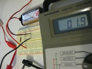
If you divide 9 volts by 4,700 ohms (a standard resistor value) you get about 1.9 mA. If you build the circuit above and short the leads, this is how much current will flow through the resistor.
i=e/r 9/4700 = 0.001915A or 1.9mA

(4,700 ohm resistor in series with 9 volt battery. Closed circuit.)
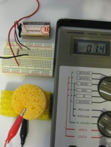
If you use the same circuit above and connect and press saline wetted sponges together, so current flows through the sponges, current will be about 1.5 mA (varies with sponges).

(4.7k resistor in series with a 9 volt battery, sponges touching)
In an actual tDCS session with the above setup, current drops even further to about 0.5mA due to skin, skull, etc. resistance. This is below what researchers are commonly using.
A better alternative would be to use a 1,000 ohm (1k) resister in series with each lead of the battery. When shorted, the current flow will be 9 volts /2000 ohms = 0.0045A or 4.5mA
Saline wetted sponges connected and touching will result in about 3.5mA flow (depending sponges used.)
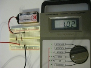
In an actual tDCS montage, current will be in the vicinity of 1 mA (depending on patient, sponges, etc.) However, current flow must be monitored!

(Montage in progress: 9 volt battery, 1k resistor in each battery lead, saline wetted sponges)
IMPORTANT: You can expect current to rise about 25% or more during a 20 minute session – for example, from about 1mA to 1.25mA due to saline water penetration of the skin and other factors. Thus you MUST monitor with a DVM.
Design #2: Using an LM317 Voltage Regulator – from http://brmlab.cz/project/brain_hacking/tdcs DESIGN NOT RECOMMENDED… See below.
This design is widely copied and tweaked for various feature enhancements. Note that a 9 volt battery is used as the source and a widely available LM317 voltage regulator is used to control current and prevent it from rising as it did in the design above. Current setting is controlled by a resistor connected to pin 1 and 2 of the LM317.
What value to use? I suggest a FIXED resistor of about 150 ohms in series with VARIABLE resistor (called a potentiometer) with a rating of about 2k or more ohms should give you the flexibility you need to get about 1 mA during a treatment session. The fixed resistor provides an upper safety limit of about 8 mA to shorted leads.
You will need a DVM in series with the anode (positive) lead in order to verify current being delivered by the system. 1 mA is the target and once the potentiometer is adjusted to achieve it, the regulator should keep it pretty close. Watch the DVM.
CAUTION: There is concern on the web that the LM317 regulator used in the brmlab.cz design may not be “stable” at low current levels. Some have suggested that the LM334 is a better, safer, regulator choice. The “GoFlow” design (below) uses the LM334.

(The brmlab.cz design also incorporates an on/off switch and a little LED battery test circuit.)
(brmlab.cz design built from Radio Shack parts)
Design # 3: GoFlow – http://flowstateengaged.com/
The folks involved with GoFlow have an ambitious plan to release a tDCS kit to the market fairly soon. Assuming they can get it going, they probably will sell as many as they can make! They have released the schematic for their device so that anyone can build a rough equivalent.
The GoFlow design uses an LM334 regulator to maintain a constant current. Rather than use a variable resistor, the GoFlow uses four fixed resistors of different values connected to a multi-position switch. The intent is to offer treatment levels from 0.5 mA to 2.0 mA.
The only thing the GoFlow design lacks is a way to monitor the current actually entering your head. If you build your own from scratch, you can simply connect a DVM in series with the anode (positive) lead. Problem solved.
Conclusion
If you are going to build your own tDCS device, your focus should be on safety. Part of being safe is knowing what your are putting in your head! I’ve mentioned several times the importance of using a DVM – but you can also use a panel meter, available from many sources to monitor the very low current of a tDCS session.
(0-3 mA Panel Meter, about $7 on EBay)
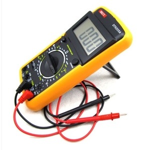
However, a DVM is still a good and easy to obtain tool. They are commonly $20 to $50 at Radio Shack, on EBay, etc.
(Example Digital Volt Meter, DVM)
Building a tDCS device? Use your head!


Thank you for your blog. The suggestion to use the DVM was excellent.
I placed a potentiometer between the battery and the breadboard on the positive lead and then placed the DVM between the breadboard and my brain on the positive lead.
The potentiometer allows me to slowly bring the amps upward and keep it under control, but the potentiometer bleeds between .35 and .55 amps as soon as I connect the battery. This may not be a bad thing.
On the breadboard there is a 1-komh (1/8 watt) resistor on the positive lead, and another going away on the negative lead.
As for results, I started this to improve concentration, but I was surprised to find that my mood has changed remarkably.
I have a couple of questions for you.
My biggest problem is figuring out how to get the salt levels correct. The figures I have seen are measured with a salinity(?) electronic measuring device. If I can’t afford a tDCS device, it is unlikely that I can afford a salinity device. For comfort, I would like a more practical way of measuring salt levels. Any ideas? For example, add a teaspoon of pickling salt to two cups of water.
I would like to incorporate the LM334, but locating a couple without buying a mass quantity is tough. Who do you purchase from?
Again, thanks for your work.
Are you sure you have the pot in series with the 1k resistor on the positive lead? You should see no current on the meter until the circuit is completed by placing the sponges (or touching the sponges together).
The salinity of the water does not seem critical. Better less salt than too much. I’ve seen posts where plain water is used instead of saline. A pinch of salt in 16 oz of water is plenty to raise the conductivity of the water.
I ordered LM334’s via EBay. You can get several for $10 including shipping.
Be safe.
Brent
You can purchase individual LM334Z at digikey for less than $1
http://www.digikey.com/product-detail/en/LM334Z%2FNOPB/LM334ZNS%2FNOPB-ND/6215
I got mine free of charge (delivery was free too) from TI.
I was googling on LM334, found TI page where I could get samples. Google “TI samples LM334”
I’d avoid buying semiconductors on eBay for something life/mission critical. LM334s are a mature enough part that samples from TI are probably from production runs, and parts bought from Mouser or Digi-Key are likely to be, as well. Parts sold by brokers are sometimes “floor sweepings” or “seconds”, and unless you’re manufacturing (and even then), peace of mind is worth a lot. 🙂
The critical part for me that I bet a lot of homebrewers wouldn’t bother with is the 5 mA fuse. I bet they’re expensive and-or hard to buy in small quantities, but in the event something goes wonky they’re a super good idea. I might even series two of them if I were particularly concerned about single-point failure.
I withdraw my comment about the point at which the fuse will blow – I may have misunderstood the interrupt rating. Please still provide examples of appropriate fuses if anyone should locate one. The ones I find in this range are extremely cost prohibitive.
10 mA fuses are expensive – but they occasionally show up on eBay at a much lower price.
Brent
Use a 1.4mA current limiting diode. They cost about $1.00
Voltage regulators are more expensive, more complicated to wire and don’t address the reall issue…limiting CURRENT.
A CLD will automatically adjust it’s resistance to maintain it’s rated value.